
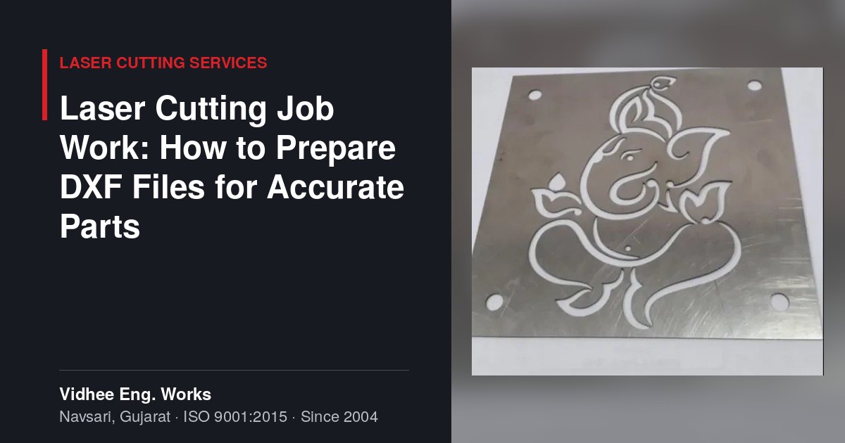
A laser cutting machine follows your drawing exactly, mistakes included. For laser cutting job work, the quality of the DXF or DWG file you send decides how accurate the parts are, how quickly they can be quoted and how much material ends up as scrap. This guide explains what a clean, cut-ready drawing looks like and which details help a job shop price your parts correctly.
When you outsource laser cutting, the programmer imports your file into CAM software, assigns cutting paths, adds lead-ins and nests the parts on a sheet. Every problem in the file, such as an open contour, a duplicated line or a wrong scale, has to be found and fixed by hand before cutting starts. A missed problem shows up as a scrapped sheet or a part that does not fit.
The cost of a laser cut part is driven mainly by three things: the material used, including the skeleton left after nesting; the total cutting length; and the number of pierces. A clean, correctly scaled drawing lets the programmer optimise all three. Our laser cutting services page shows the kind of flat parts that are typically cut from sheet.
The laser cuts along continuous paths, so every outline and every internal cut-out must be a single closed contour. Even a tiny gap between two line ends can make the software skip the feature or treat it as an open line.
Export the part flat, in its unbent state. An older ASCII DXF version is the safest choice.
Drawings usually carry title blocks, dimensions, notes and bend lines as well as cut geometry. If these share a layer with the outline, the programmer must separate them by hand. A simple layer structure avoids this.
| Layer | Contents | What the shop does with it |
|---|---|---|
| CUT-OUTER | Outer profile of each part | Cut through, last |
| CUT-INNER | Holes, slots and internal cut-outs | Cut through, first |
| MARK | Part numbers, logos, alignment marks | Engrave or mark only, not cut |
| BEND | Bend lines with direction and radius noted | Used for checking and bending, not cut |
| NOTES | Dimensions, title block, text | Reference only, ignored by the machine |
Bend lines need special attention. If the part will be bent after cutting, note the bend direction (up or down) and the inside radius, or better, send the 3D model. Parts that move on to CNC press brake bending need a flat pattern developed for the actual material and tooling, not a generic one.
The laser beam removes a narrow strip of material called the kerf. Its width is a fraction of a millimetre and varies with material and thickness. The CAM software offsets the cutting path by half the kerf so that the finished part matches the drawn size. This is why you should always draw parts to their final nominal dimensions. Do not add or subtract kerf yourself; the compensation would be applied twice and parts would come out undersized or oversized.
If two parts must fit together, such as a tab into a slot, describe the required fit in a note rather than adjusting the geometry by eye. The shop can then set the clearance to suit its cutting parameters.
Very small holes and thin webs cause the most trouble. As a hole diameter approaches the sheet thickness, heat builds up, the hole may taper or fail to clear, and thin bridges between features can warp. The table below gives general rule-of-thumb guidance; real limits depend on the material, the machine and the assist gas.
| Feature | General guidance | Reason |
|---|---|---|
| Hole diameter in mild steel | At least equal to sheet thickness | Smaller holes may taper or not cut through cleanly |
| Hole diameter in stainless steel or aluminium | Around 1.5 to 2 times thickness | These materials hold heat and reflect more of the beam |
| Hole edge to part edge | At least equal to thickness | Prevents bulging and burn-through at the edge |
| Web between two cut-outs | At least equal to thickness, more for long webs | Thin webs distort from heat |
| Slot width | At least equal to thickness | Narrow slots can fuse or not clear |
Where a precise hole is needed for a bearing, dowel or tapped thread, it is often better to laser cut an undersized pilot and finish it by drilling or reaming.
Nesting is the arrangement of parts on a standard sheet to use as much material as possible. On a 2500 x 1250 mm bed, many small parts can be nested together, while larger panels may be cut one or two to a sheet. You can help the shop nest well and quote accurately by giving:
Vidhee Eng. Works has been in sheet metal work at New GIDC, Kabilpore, Navsari since 2004 and runs CNC fiber laser cutting in-house under an ISO 9001:2015 certified quality management system, with dispatch across India by road. Send us your drawing in DXF, DWG, STEP or PDF with material, thickness and quantity, and we will come back with any questions and a quote.
Send your drawing, material and quantity to Vidhee Eng. Works, Navsari, and get a clear quotation with a delivery date.
A DXF or DWG of the flat part at 1:1 scale in millimetres is the most direct format, because it imports straight into the cutting software. STEP files are useful when the part will be bent, since the flat pattern can be developed from the 3D model. PDFs and sketches are also accepted, but they have to be redrawn, so include every dimension clearly.
No. Draw every part to its final nominal size. The cutting software offsets the beam path by half the kerf width automatically, based on the material, thickness and cutting parameters. If you also adjust the geometry, the compensation is applied twice and the parts come out the wrong size. For fits such as tabs and slots, add a note describing the fit you need.
As a general rule of thumb, keep hole diameters at least equal to the sheet thickness in mild steel, and around 1.5 to 2 times the thickness in stainless steel and aluminium. Smaller holes may be possible depending on material and settings, but they can taper or cut poorly. For critical holes, laser cut a pilot and drill or ream it afterwards.
Send clean, closed geometry so no programming time is spent repairing files. Reduce the number of pierces and the total cut length where the function allows, avoid unnecessary tight tolerances, and order in batches that nest well on a standard sheet. Grouping parts of the same material and thickness in one order also helps the shop use sheets efficiently.
Share your material, thickness and quantity — we’ll review it and come back with a quote and a delivery date, not just a price.