
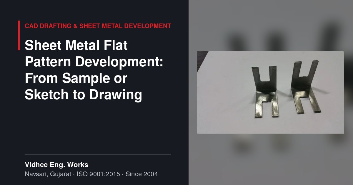
Many sheet metal jobs do not begin with a neat CAD model. They begin with a worn-out sample from a machine, a sketch on graph paper, or a photocopied drawing from the 1990s that nobody can fully read. This article explains how that starting point is turned into a drawing and flat pattern that can be cut, bent and repeated with confidence.
A sample shows what a part looks like today, not what it was meant to be. Edges may be worn, flanges may have sprung open, holes may have been enlarged by hand during an old repair. A sketch usually captures the outer shape but leaves out material grade, thickness, inside bend radius and which dimensions actually matter for fit.
Old drawings bring their own problems: imperial units mixed with metric, missing views, notes that refer to a machine that no longer exists, or dimensions that were changed on the shop floor and never updated. A manufacturing drawing has to settle all of these questions in one place so that the laser operator, the press brake operator and the inspector read the same intent.
Good reverse engineering starts with deciding what to measure before picking up the caliper. The useful sequence is:
Photographs with a scale or ruler in the frame are very useful later, especially for parts with several bends in different planes.
Sheet metal flat pattern development is the step of working out the exact flat blank that, once bent, gives the finished dimensions. It is where most first-time errors come from, because the metal stretches on the outside of a bend and compresses on the inside.
Somewhere inside the thickness there is a layer that neither stretches nor compresses: the neutral axis. The K-factor expresses where that layer sits as a fraction of thickness, measured from the inside face. For common air-bending work it generally falls somewhere between about 0.3 and 0.5, depending on material, thickness, radius and tooling.
The bend allowance is the length of the neutral axis through the bend. As general guidance it is calculated as: bend allowance = (π / 180) × bend angle × (inside radius + K-factor × thickness). Bend deduction is the amount taken off the sum of the outside flange lengths to get the flat length. CAD software applies these values automatically, but only if the K-factor or bend table matches the material and the press brake tooling that will actually form the part.
This is why a flat pattern drawn for one shop's tooling may not give the same result on another shop's press brake. When a flat pattern is developed against the tooling that will bend it, and a first piece is checked, the values can be fine-tuned before a batch is cut.
A clear sheet metal drawing usually carries the formed part in front, top and side views, an isometric view for orientation, and the flat pattern on the same sheet or a second sheet with bend lines, bend directions and angles marked.
Dimension the features that matter for function from the chosen datums, and avoid dimensioning the same feature twice in different ways. The title block and notes should state:
Once a drawing is approved, every change should raise the revision letter or number, with a short note in the revision table explaining what changed and why. The file name, the title block and the cut file (DXF) should all carry the same revision.
Superseded revisions should be marked clearly and kept for reference, not deleted, because spares for older machines may still need them. Most repeat-order mistakes in fabrication come from an old DXF being reused after the drawing was updated, so linking the cut file to the drawing revision is a simple, effective habit.
Different formats serve different purposes. Sharing the right combination saves a round of questions. A CAD drafting and sheet metal development service can work from any of these, or from a sample or sketch alone.
| Format | What it carries | Best used for |
|---|---|---|
| DXF | 2D geometry, usually the flat pattern | Direct input for laser cutting; needs a drawing alongside for bends |
| DWG | 2D drawing with layers, dimensions and notes | Full manufacturing drawings from AutoCAD-type systems |
| STEP | 3D solid model, software-neutral | Formed parts and assemblies; flat pattern can be developed from it |
| Fixed drawing image with dimensions and notes | Approval, inspection reference and shop-floor copies | |
| Sample, sketch or photo | Physical reference or rough intent | Reverse engineering, replacement parts and early ideas |
For a new product that is still evolving, the drawing usually goes through a few iterations alongside physical samples; our prototype and custom product manufacturing page covers how that stage is handled.
Vidhee Eng. Works has been fabricating sheet metal in Navsari, Gujarat since 2004, with CAD drafting, flat-pattern development, laser cutting and press brake bending under one roof and an ISO 9001:2015 certified quality system. Send us your drawing, sketch or sample details through our contact page, and we will help turn it into a drawing you can reorder against, with dispatch across India and export job work possible.
Send your drawing, material and quantity to Vidhee Eng. Works, Navsari, and get a clear quotation with a delivery date.
Yes. A physical sample is a common starting point. The part is measured from stable reference faces, material and thickness are identified, and bend angles and radii are recorded. A drawing and flat pattern are then prepared and shared for your approval before any production cutting, so you can confirm that the functional dimensions and hole positions match your assembly.
The K-factor describes where the neutral axis lies within the sheet thickness during bending. It is used to calculate bend allowance and therefore the flat blank length. If the K-factor does not match the actual material and press brake tooling, the bent part will come out slightly long or short, so it should be set for the real process, not left at a software default.
If you have a 3D model, a STEP file plus a PDF drawing is ideal. For flat parts, a DXF with a PDF showing material, thickness and quantity works well. DWG files are also accepted. If you have none of these, a dimensioned sketch, clear photographs with a scale, or the sample itself can be used to create the drawing.
Every approved change raises the revision on the drawing, the title block and the cut file together, with a short note recording what changed. Older revisions are marked as superseded and kept for reference. Linking the DXF used for cutting to the drawing revision is the simplest way to stop an outdated file from being used on a repeat order.
Share your material, thickness and quantity — we’ll review it and come back with a quote and a delivery date, not just a price.