
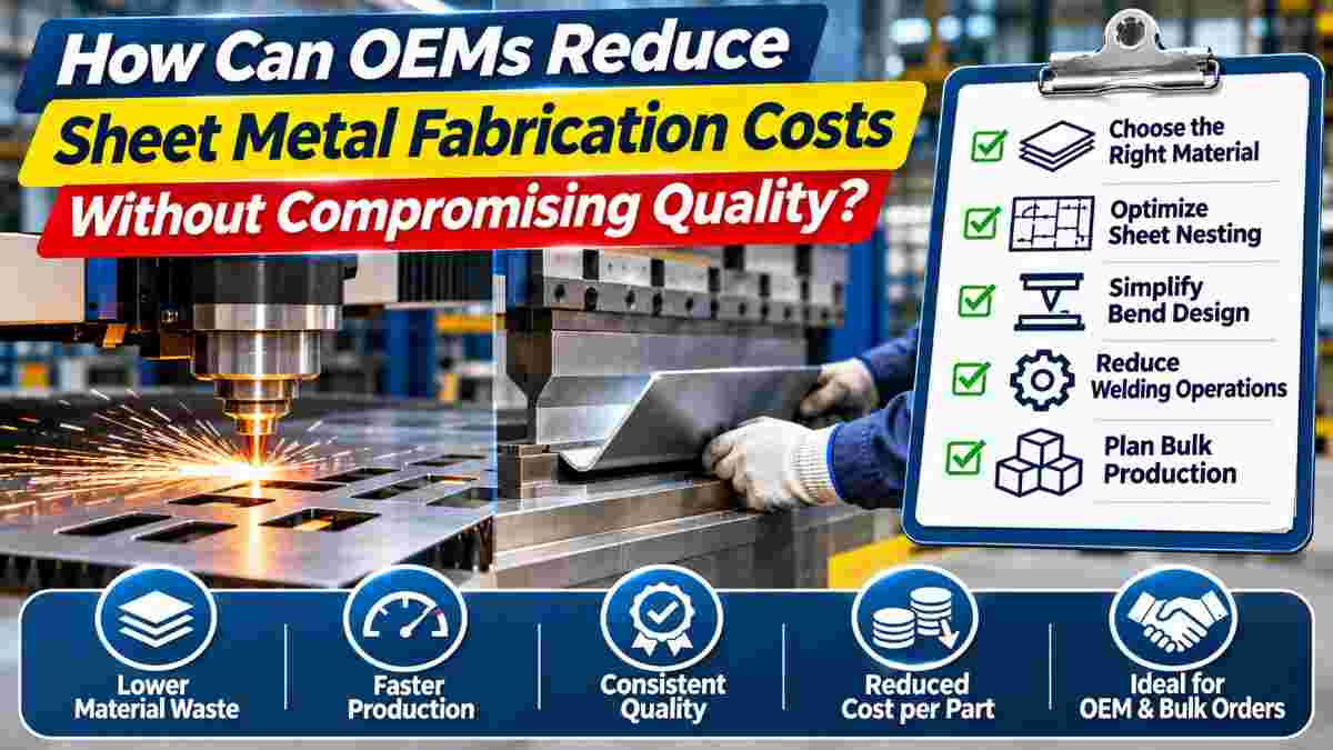
A sheet metal component may look simple in a CAD drawing, but manufacturing costs can increase quickly when the design involves unnecessary bends, excessive material thickness, tight tolerances, or complicated welding requirements.
For Original Equipment Manufacturers (OEMs), these small design decisions become more significant during bulk production. An additional manufacturing operation that adds only a few minutes per component can create substantial expenses across hundreds or thousands of parts.
The challenge is finding ways to reduce sheet metal fabrication costs without affecting product strength, dimensional accuracy, durability, or assembly performance.
Cost-effective fabrication does not mean selecting the cheapest material or removing essential quality checks. Instead, it involves improving how parts are designed, manufactured, inspected, and delivered.
This guide explains practical strategies OEM engineers and procurement teams can use to control fabrication costs while maintaining reliable product quality.
Sheet metal fabrication costs depend on material requirements, component geometry, manufacturing processes, production quantity, and quality expectations.
A typical fabricated component may pass through several operations, including cutting, bending, welding, finishing, and inspection.
Each operation adds machine time, labor, handling, and sometimes additional tooling costs.
The main cost factors include:
Material grade and thickness
Sheet utilization and scrap generation
CNC laser cutting time
Number and complexity of bends
Welding and assembly requirements
Surface finishing
Dimensional tolerances
Production batch size
Quality inspection requirements
Packaging and transportation
For example, two electrical enclosures manufactured from the same mild steel sheet may have different production costs if one requires more bends, welding operations, and precision features.
Understanding these cost drivers allows OEMs to identify improvements before production begins.
Material selection is one of the earliest opportunities to control manufacturing expenses.
Different metals have different purchase prices, mechanical properties, corrosion resistance, and fabrication characteristics.
Common sheet metal fabrication materials include mild steel, stainless steel, aluminum, and galvanized steel.
Mild steel is commonly used for industrial brackets, machinery covers, frames, and equipment enclosures because of its availability and suitability for cutting, bending, and welding.
It may be more economical than stainless steel when corrosion resistance can be achieved through a suitable protective coating.
However, material selection should consider the component's intended operating environment.
Stainless steel generally has a higher material cost than ordinary mild steel.
It can also require different cutting, bending, and welding procedures.
However, stainless steel may provide better long-term value in applications where corrosion resistance is important.
For equipment exposed to moisture, cleaning chemicals, or particular industrial environments, selecting the appropriate stainless steel grade may reduce future maintenance or replacement requirements.
Increasing sheet thickness generally increases raw material weight.
Thicker sheets may also require greater cutting power and bending force.
For example, increasing a component's sheet thickness from 2 mm to 3 mm increases its theoretical material volume and weight by 50%, assuming the same flat dimensions and material density.
However, the cost increase will not necessarily be exactly 50%, because production costs also depend on processing and material utilization.
Engineers should select thickness according to load calculations, component stiffness, bending requirements, and relevant safety factors.
Laser nesting is the arrangement of multiple component profiles on a sheet to improve material utilization.
An efficient nesting layout can reduce scrap and increase the number of parts produced from each sheet.
For OEMs ordering multiple components, this can be an important opportunity to lower material consumption.
Imagine that one cutting layout uses only 70% of a metal sheet, while an improved arrangement uses 85%.
The second layout may allow more usable components to be produced from the same material, depending on geometry, required spacing, and production quantities.
However, nesting efficiency should not be optimized at the expense of cutting quality or part stability.
Useful strategies include:
Grouping parts made from the same material and thickness
Reviewing part orientation
Reducing unnecessary gaps where technically feasible
Combining compatible production requirements
Planning orders to improve sheet utilization
Using approved common-line cutting where suitable
Standardizing material sizes when practical
Engineers should also consider grain direction, surface finish, thermal distortion, and part geometry before approving a nesting layout.
Vidhee Eng. Works offers CNC laser cutting services for industrial sheet metal components, supporting precision cutting requirements and bulk manufacturing.
CNC press brake bending is a common operation in sheet metal manufacturing.
Bending costs depend on the number of bends, part size, material characteristics, tooling, setup time, and handling requirements.
A component requiring multiple setups or special tooling may cost more than a similar part designed around standard bending operations.
Using consistent bend radii can reduce tooling changes and simplify production.
For example, a fabricated enclosure containing several bends with similar radii may be easier to manufacture than one requiring multiple different forming tools.
However, the minimum allowable bend radius depends on material grade, thickness, temper, and forming direction.
The design should respect these requirements.
Yes. Reducing unnecessary bends may shorten production time and simplify quality inspection.
However, bends can also provide stiffness or eliminate the need for welded joints.
Therefore, engineers should evaluate the complete manufacturing process rather than removing bends solely to reduce press brake operations.
A well-designed folded component may be less expensive than an assembly requiring multiple individual parts and welding operations.
The order in which bends are formed can affect whether a part can be manufactured using standard tooling.
Poorly planned geometries may cause collisions between the formed component and press brake equipment.
A design-for-manufacturing review can identify these problems before cutting begins.
OEMs can use CAD drafting and sheet metal development services to review flat patterns, bend allowances, and forming requirements before production.
Design for Manufacturing (DFM) is the process of reviewing a product design to ensure that it can be manufactured efficiently using suitable equipment and processes.
DFM helps identify unnecessary complexity, difficult features, and manufacturing risks before production.
Common examples include:
Very small holes in thick sheets
Narrow slots requiring special processing
Tight bends that exceed material capabilities
Complex profiles with excessive cutting length
Holes positioned too close to bend lines
Unnecessary welding joints
Difficult-to-access assembly points
Tight tolerances on noncritical dimensions
These features may require slower processing, specialized tooling, additional inspection, or rework.
Engineers can consider:
Using standard material thicknesses
Reducing unnecessary cutouts
Simplifying bend geometry
Standardizing hole sizes
Designing components for easier assembly
Reducing separate fabricated parts where appropriate
Using available manufacturing processes and tooling
Any design changes should preserve the component's required functionality and structural performance.
Tolerances define the allowable variation in a finished component's dimensions.
Tight tolerances may require additional setup time, careful process control, specialized fixtures, and more detailed inspection.
For example, a bracket that must fit precisely into a mechanical assembly may require tight positional tolerances.
However, applying those same tolerances to every noncritical dimension can unnecessarily increase costs.
Engineers should distinguish between functional dimensions and general dimensions.
Critical dimensions may include mounting holes, mating surfaces, alignment features, and component interfaces.
Other dimensions may allow greater variation without affecting product performance.
A practical drawing should clearly indicate:
Critical dimensions
Appropriate dimensional tolerances
Bend angle requirements
Flatness requirements where necessary
Surface finish requirements
Relevant geometric tolerances
This allows fabricators to focus resources on the features that matter most.
Welding costs depend on joint design, material thickness, weld length, access, preparation, and inspection requirements.
A design involving several separate components may require additional fit-up, clamping, welding, and finishing.
Yes. In some cases, a component can be redesigned to use formed features instead of multiple welded parts.
For example, a bracket assembled from several flat plates may sometimes be manufactured as a single bent component.
This may reduce welding time and improve assembly consistency.
However, the redesigned part must still meet the required strength and performance criteria.
Self-locating tabs and slots can help align components before welding or fastening.
When appropriately designed, these features can reduce manual positioning and improve repeatability.
They can be particularly useful in high-volume fabrication involving repeated assemblies.
Production quantity influences the cost per component because setup and programming expenses can be distributed across multiple parts.
For example, a CNC laser cutting job may require programming, material preparation, and machine setup whether the order contains 20 or 500 components.
Producing a larger batch may reduce the setup cost allocated to each part.
However, larger orders are not automatically more economical overall.
They may create inventory costs, storage requirements, and additional working capital needs.
Not necessarily.
The appropriate order quantity depends on demand forecasts, production schedules, storage capacity, and material availability.
OEMs should compare the benefits of larger production batches against inventory and cash-flow requirements.
Repeat orders can improve production planning when drawings, material specifications, and acceptance criteria remain consistent.
Approved manufacturing instructions and established inspection procedures can reduce uncertainty during subsequent batches.
However, any design revision should be controlled carefully to prevent the wrong version from entering production.
Prototyping allows engineers to validate component dimensions, fit, form, and manufacturing feasibility before committing to larger production quantities.
Although prototype manufacturing adds an initial expense, it can help identify problems that would otherwise affect the entire production batch.
Important checks include:
Dimensional accuracy
Bend angles and radii
Assembly fit
Material suitability
Structural performance
Mounting hole alignment
Welding accessibility
Surface finishing requirements
For critical components, additional functional testing may be necessary.
First-article inspection involves examining an initial manufactured component or batch to confirm conformity with approved requirements.
It helps identify production-related issues before full-scale manufacturing begins.
For OEMs, an approved first article can establish a reference for subsequent production, provided the manufacturing process and specifications remain appropriately controlled.
Manufacturing defects can affect profitability through wasted materials, additional labor, delayed deliveries, and replacement production.
Common defects include dimensional inaccuracies, incorrect bends, rough cutting edges, welding distortion, and surface damage.
Preventing these problems requires clear technical requirements and consistent inspection.
Quality control helps identify defects before parts proceed to additional manufacturing stages.
For example, checking laser-cut blanks before bending may prevent defective parts from receiving further processing.
Likewise, inspecting bent components before welding can reduce assembly-related rework.
Useful practices include:
Incoming material verification
First-article inspection
In-process dimensional checks
Welding quality inspection
Final component inspection
Proper handling and packaging
Vidhee Eng. Works describes its manufacturing outsourcing process as including drawing reviews, in-house production, and batch inspection under its ISO 9001:2015 quality system.
Manufacturing outsourcing can help OEMs access specialized equipment and production capabilities without investing in additional machinery or factory capacity.
For example, a company may need CNC laser cutting, press brake bending, and welding for a new product but may not have sufficient production volume to justify purchasing all the necessary equipment.
Outsourcing these operations can reduce capital investment and provide more flexibility when demand changes.
However, outsourcing costs should be evaluated alongside supplier quality, lead times, logistics, communication, and production reliability.
Important considerations include:
Relevant manufacturing equipment
Experience with similar components
Drawing review capabilities
Material handling procedures
Quality management processes
Production capacity
Delivery reliability
Communication and technical support
A supplier that can coordinate multiple fabrication processes may also help reduce handoffs between different vendors.
Vidhee Eng. Works' engineering and manufacturing outsourcing services support OEMs requiring individual fabrication processes or coordinated manufacturing for industrial parts.
A detailed Request for Quotation (RFQ) helps suppliers understand the manufacturing requirements and prepare accurate quotations.
Incomplete specifications may lead to pricing assumptions, revisions, and production delays.
OEMs should include:
Material type and grade
Sheet thickness
Approved CAD files and technical drawings
Required production quantity
Critical dimensions and tolerances
Cutting and bending requirements
Welding and assembly specifications
Surface finishing requirements
Inspection and testing expectations
Prototype approval requirements
Packaging and delivery conditions
Buyers can also ask suppliers to identify potential cost-saving design changes without altering critical product requirements.
This approach encourages technical collaboration rather than relying only on price negotiations.
The most effective approach is to review material selection, part geometry, manufacturing operations, tolerances, and production quantities together. DFM reviews can identify opportunities to reduce unnecessary processing and material waste.
Larger orders can reduce per-part setup costs and improve production efficiency. However, the financial benefit depends on manufacturing complexity, material utilization, inventory costs, and delivery requirements.
CNC laser cutting can be cost-effective for many production volumes, especially for complex profiles and parts that do not justify dedicated stamping tools. For very high-volume simple parts, other processes may sometimes offer lower unit costs after tooling investment.
Yes, when the thinner material meets the required structural, stiffness, and durability requirements. Using insufficient thickness can create quality problems and additional reinforcement costs.
Tight tolerances may require additional machine setup, process control, fixtures, and inspection. Engineers should specify tighter tolerances only where they are necessary for product function.
The answer depends on production volume, available equipment, capital investment, technical requirements, and operational priorities. Outsourcing can provide flexibility, but supplier capability and quality control should be evaluated carefully.
Reducing fabrication expenses requires more than finding the lowest quotation. The best results come from selecting appropriate materials, designing manufacturable components, reducing avoidable operations, and maintaining consistent quality.
Vidhee Eng. Works, located in GIDC Kabilpore, Navsari, Gujarat, provides industrial sheet metal fabrication, CNC laser cutting, press brake bending, welding, and manufacturing outsourcing services.
The company supports custom industrial components, electrical enclosures, machine covers, brackets, fabricated assemblies, and recurring OEM production requirements.
Its services include design review, fabrication planning, production, inspection, and dispatch for industrial customers.
For OEMs looking to improve material utilization, simplify fabrication, or manage bulk production requirements, reviewing the design with an experienced manufacturing team can help identify practical improvements.
Need a Cost-Effective Sheet Metal Fabrication Partner?
Contact Vidhee Eng. Works with your drawings, material specifications, quantity, and delivery requirements.
Discuss your design and production needs to explore opportunities for efficient, repeatable, and quality-focused sheet metal manufacturing.
Share your material, thickness and quantity — we’ll review it and come back with a quote and a delivery date, not just a price.